Sextant Errors And Corrections: With Downloadable PDF
A properly adjusted sextant is an incredibly precise scientific instrument. Unfortunately, it is subject to a large number of potential errors. All these errors need to be reduced or eliminated before you can use it to its full potential. In this article, I am going to walk you through all the different sources of error and explain how to correct them.
We can divide the errors of a sextant up into two categories, correctable and non-correctable.
| Correctable Errors | Non-Correctable Errors |
| Perpendicularity Error | Collimation Error |
| Side Error | Centering Error |
| Index Error | Prismatic Error |
| Shade Error | |
| Graduation Error | |
| Prismatic Error |
There are lots of potential errors to account for before you can start taking sights, but we have only listed three of them as correctable.
The three correctable errors can be worked through in turn, reducing them all down to a minimum. Any residual error gets applied to all of your sights as “Index Error”.
The other, non-correctable, errors are out of your control. They come from the manufacturing process, so depend entirely upon the quality of the sextant you are using. Manufacturers will tell you the “Instrument Error”, which is the total of all these non-correctable errors.
I have prepared a downloadable PDF which summarises all these sextant errors and gives you brief instructions for making the required corrections. It has been designed to be kept with your sextant for easy reference when taking sights.
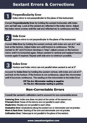
Perpendicularity error
In a sextant, perpendicularity error is caused when the index mirror is not perpendicular to the plane of the instrument.
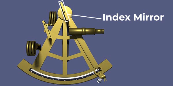
The index mirror is mounted on the end of the index arm. To take measurements with the sextant, you move the index arm, which in turn moves the index mirror. The graduations on the arc of the sextant measure the angle that you have moved the index arm, and mirror to.
Pro Tip: The angle that you move the index arm is only half of what the reading says. This is because the sextant works on the principle of double reflection.
If the index mirror is not perpendicular to the plane of the instrument, the beam of light does not travel in a flat line across the surface of the instrument.
Not only does it introduce inaccuracies in the measurement you take, but it also makes it much harder to take sights. The reflected image will not line up with the true image.
The error of perpendicularity is the first one you need to correct. If you don’t correct for perpendicularity first, it will impact your corrections for the other errors.
Correcting perpendicularity error on a sextant
To correct your sextant for perpendicularity error, you start off by setting the index arm halfway. Anywhere between 30° and 70° should be suitable.
With the arm set, you turn the sextant onto its back and look at the arc. The arc is the part of the sextant that has all the graduations written on it.
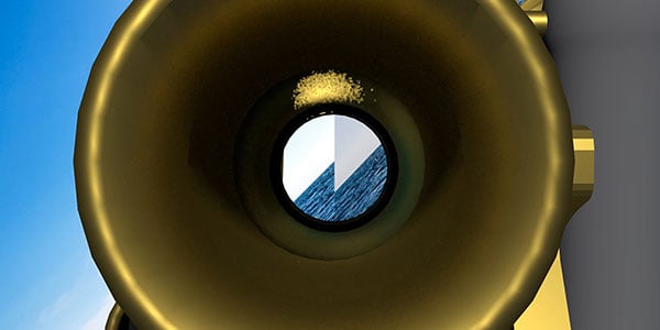
You need to check to see whether the true arc and the reflected arc are continuous. They will either be continuous, meaning there is no perpendicularity error, or they will have a step, indicating perpendicularity error is present.
If your checks reveal that perpendicularity error is present, you need to adjust the screw on the side on the index mirror. There is usually only one screw present on an index mirror, so you just need to turn that one.
Pro Tip: With all sextant mirror adjustments, always turn the screw that is on the top in whatever orientation you hold the sextant.
While adjusting the screw, continue watching the image in the index mirror and compare it to the true arc. Once they are in line, appearing as a continuous curve, you have removed as much perpendicularity error as you can.
Removing perpendicularity error beings the index mirror perpendicular to the plane of the instrument.
Side Error
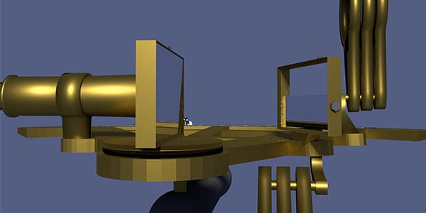
In a sextant, side error is caused when the horizon mirror is not perpendicular to the plane of the instrument.
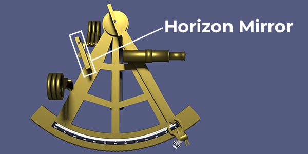
The horizon mirror frame is mounted rigidly to the frame of the sextant. Within the horizon mirror frame, the mirror itself can move and be adjusted with two screws.
When it isn’t perfectly adjusted, it can create two errors: side error, and index error.
Side error is the part that we deal with in this step. It is the part created when the mirror isn’t perpendicular to the plane of the sextant.
Correcting side error on a sextant
Correcting side error is an iterative process. When you correct for side error, you introduce a bit of index error. Similarly, when you continue adjusting screws to correct the index error you reintroduce a bit of side error.
Your goal in this step is to reduce the side error to the minimum you can.
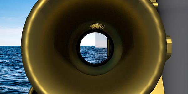
Start by setting the sextant to 0°, and looking at the horizon. When looking at the horizon, you need to tilt your head 45° to the right.
If side error is present, there will be a step in the horizon. In the image above, I have put in a lot of side error for illustration purposes. In reality, your horizon may only be slightly out of step.
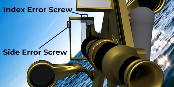
To eliminate this side error, you adjust the “side error screw”, on the side of the horizon mirror. As your head is tilted, this screw appears to be on top. Keep looking through the sextant until you bring the horizon back into line.
Once it is lined up, you can bring your head back vertical. You will then be presented with one of two possibilities. Either the horizon is still in line, or it isn’t. If it is in line, then you have eliminated all the errors on your sextant. More likely, the horizon now has another step in it.
If you have introduced some index error, you need to adjust the other screw on the horizon mirror, the “Index Error Screw”. Keep looking through the sextant until the horizon is in line again.
Once you have aligned the horizon using the “Index Error Screw”, you can tilt your head back to 45°. You are now checking whether you have introduced more side error while correcting for the index error.
This is the iterative process of correcting for side error. You keep alternating between correcting both screws, alternating the sextant between vertical and 45° as you do. When you have removed as much error as possible, your final correction will be at 45°, with the “Side Error Screw”. You need side error to be eliminated as you can account for the final bit of index error in the next stage.
Index Error
In a sextant, index error is caused when the horizon mirror is not parallel to the index mirror when the instrument is set at 0°.
When the instrument is set at 0°, the horizon mirror and the index mirror should show the same image. If both are looking at the horizon, it should be perfectly in line.
We introduced the concept of index error while we were correcting for side error, eliminating the correctable elements of it. Once we finished eliminating the side error, we accepted any residual separation of the horizon as index error.
The reason we accepted the last bit of index error is that we can account for it mathematically. Our iterative process before has already taken out what we can, so the final index error correction is just getting a precise measurement of what is left.
Correcting index error on a sextant
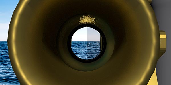
To correct for index error, you first need to work out if it is present. Set the sextant to 0° and then focus on something in the distance. The horizon is ideal.
If the horizon looks continuous, the sextant has no index error. If there is a step in the horizon, index error is present.
If index error is present, you simply adjust the micrometre drum while looking down the telescope. Your goal is to make the horizon continuous again.
When the horizon is continuous, your index arm is set in the correct position for reading off the index error.
You read what the micrometre drum of the sextant is set to, and that is your index error.
The index error is composed of two parts. You have the absolute value, and you have the direction. To find the direction, we check whether the reading is on, or off the arc.
When a reading is “on the arc”, it means that you have moved onto the graduations, just as you would when measuring the altitude of a star.
When a reading is “off the arc”, it means you have moved off the normal graduations, effectively the same as measuring an altitude below the horizon.

When you are applying corrections, and index error “off the arc” will need to be added to the measurement. It is the equivalent of saying the 0° setting of the sextant is a little bit further back than the graduations indicate.
Conversely, an index error “on the arc” would be applied the opposite way. You would subtract the error from all your readings.
Non-correctable sextant errors
Once your sextant is adjusted as well as possible for perpendicularity, side and index error, you are just left with non-correctable errors.
Pro Tip: I have included Collimation as a non-correctable error because that is the case on most sextants. On some older models, you can adjust the telescope and correct for collimation.
Non-correctable errors usually result from the manufacturing process. They cover things to do with the physical construction of the instrument. Rather than accounting for each one separately, manufacturers just refer to them together as the “Instrument Error”.
This total “Instrument Error” is determined during calibration, completed before you purchase the sextant. You will be told the “Instrument Error” when you receive your sextant.
Usually, there is a calibration card in the sextant’s box.
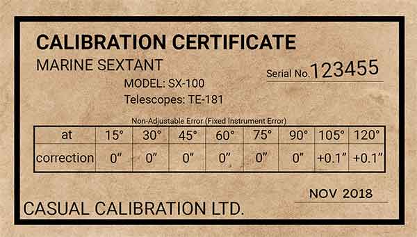
The calibration card tells you the total non-correctable errors that you can expect from your sextant. Usually, at low values, the errors will be negligible. Instrument error becomes more significant when the sextnat reaches its more extreme settings.
To correct for instrument error, you just apply the correction that the calibration certificate tells you to. In the case above, when taking readings about 97.5°, you would add on 0.1 seconds to each reading.
Collimation error
In a sextant, collimation error is caused when the telescope is not parallel to the frame of the instrument.
You may also hear collimation error referred to as “Telescope Error”. Whatever name is used, it just refers to errors in the mounting of the telescope on the main frame of the sextant.
On older sextants you would get screws to adjust the telescope, which allowed you to apply corrections for collimation. Modern sextants often do not come with these screws, which is why I now count collimation as a non-adjustable error.
When the telescope is not parallel to the frame of the instrument, the light’s path will bend slightly as it is reflected in the horizon mirror, then again in the index mirror. This bending becomes more significant as the index arm measures higher altitudes.
Put simply, the greater the angle you measure, the greater the impact from collimation.
Fortunately, modern manufacturing techniques have pretty much eliminated collimation at smaller angles. The telescope is rigidly fixed to the frame of the instrument so there is no need to adjust for collimation.
Additionally, the angles that are most useful for navigating are unlikely to be effected too much anyway.
Centering error
In a sextant, centering error is caused when the pivot point of the index arm is not perfectly aligned with the geometric center of the arc of the instrument’s frame.
There is no definite way that the error will effect the sextant, so it is not possible to say that it angles will be greater or lesser due to a centering error.
For example, it the centering point is slightly too far forward, it will have a different impact to the centering point being slightly too far back.
You do know, however, that if you have accurately set up your sextant at 0°, the further you move from 0°, the more of an impace centering will have.
As it is non-adjustable, it will have been measured during calibration and effectively eliminated.
The main concept to remember with centering error is that if the index arm feels slightly loose, centering error will be present and will impact your readings in an unpredictable way.
To prevent centering error, it is important to take care of the sextant. Any impact or damage could prevent the bearings in the index arm from keeping it perfectly centered in the geometric center of the frame’s arc.
Prismatic error
In a sextant, prismatic error is caused when the faces of the mirrors are not parallel to eachother.
A mirror is just a piece of glass that has been silvered on one side. When a beam of light hits the mirror straight on, it is reflected straight back. If the beam hits the mirror at an angle, it is still reflected straight back, but there is also a little refraction due to the refractive index of the glass.
If the surface of the glass is completely parallel front and back, the refraction as the light enters the mirror is the same as the refraction when the light leaves the mirror. They cancel out.
If the front and back of the mirror are not parallel, the light is refracted slightly differently on its inbound path compared to its outbound path.
The result is that there will be a small difference between the angle of incidence and the angle of reflection.
Modern manufacturing techniques mean that mirrors can be produced with parallel faces. If the faces are not parallel, they can be rejected and new mirrors made.
Prismatic error is checked during the commissioning and calibration of the sextant so you can effectively ignore it on most sextants.
On antique sextants, however, prismatic error can start to become significant. Glass behaves like an incredibly viscous fluid, so over time the surfaces can move.
Heat, can also have an impact of the viscosity of the glass in the mirrors. Physics tells us that the warmer the glass becomes, the more fluid it becomes. Over time, a warm mirror will deform more than a cold mirror.
Overall, we just need to rember that prismatic errors will creep in over time. The warmer the sextant is, the quicker those errors will creep in. In the typical lifetime of a sextant, however, the small differences are not going to be significant.
Shade error
In a sextant, shade error is caused when the faces of the shades are not parallel to each other and perpendicular to the plane of the instrument.
The shades are designed to be perpendicular to the plane of the instrument so that light passes through them “normally”.
You want the light to enter the shade at 90°, pass straight through, and exit at 90°. Any other angle will result in a small amount of refraction, introducing small errors in the position of the image on the mirrors.
As there are multiple shades, this has the effect of multiplying any errors.
Again, shade error should be minimised during the manufacturing process.
Over time, however, the bearings on the shades may become worn or damaged, resulting in them not sitting correctly. When this happens, shade error is likely to creep in.
The same a centering error, it is important to look after your sextant. The better it is cared for, the longer it will last before these errors start to become significant.
Graduation error
In a sextant, graduation error is caused by imperfections in the graduations of the micrometer or of the markings on the instrument’s arc.
The sextant needs graduations so that you can read the angle that you have set the index arm to. It is calibrated so that it actually reads double the angle that you have set the arm to because the sextant works on the principle of double reflection.
The graduations actually tell you the altitude of the body you are measuring so that you do not need to do extra mathematics yourself. If there are any errors in those graduations, however, it will present as errors in the angles you measure.
The graduations should have been applied correctly during manufacture and checked during calibration. There is no way for you to adjust what has been printed or engraved onto the surface of the instrument.
Worm and rack error
In a sextant, worm and rack error is caused by imperfections in the mechanism that hold the index arm in position.
The worm is the screw that you turn to move the index arm, and the rack is the teeth along the arc of the sextant. The worm slowly moves along the rack as you turn the mircometer drum.
As the gearing mechanism wears over time, small errors can creep into the worm and rack. You cannot correct for these, but it is possible to check whether they are present. Any sign of play or resistance in the gearing of the arm will be a sign that worm and rack may be present and significant.
The sextant arm should be fixed and not wiggle around when the worm is not moving.
To prevent worm and rack errors developing, you need to take good care of the sextant. Ensure you apply grease and oil at intervals specified by the manufacture. When using the sextant, make sure the arm does not grind along the rack.
If you are moving the index arm, fully release the clamp before moving it. Then stop the arm completely before releasing the clamp.
More information about correcting a sextant.
I have produced a series of videos about using the sextant. The second video in the series is dedicated to sextant errors and corrections. It guides you through each of the errors, showing you how to correct them.